|
|
 |
|
|
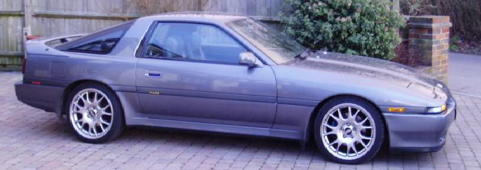
This area was a log detailing work undertaken on my original UK MA70 car as it happened. Sadly, mainly due to work conditions at the time, this area stopped being updated regularly.
I am keeping it on-line however as it is a good place fr ideas even if some of the products are now out of date now. On the other hand, much of this stuff is incorporated on my current 2.5TT JZA70 with modern products & a little more factory in implementation.
Select a project date or scroll down to view all. Click the back button to return to this page.
|
|
|
|
|
DATE
|
PROJECT
|
|
18/12/03
|
LED side and number plate lights
|
|
24/12/03
|
Xenon head lamps
|
|
25/12/03
|
LED Door markers
|
|
28/12/03
|
LED interior lamp
|
|
30/12/03
|
LED rear interior
|
|
05/01/04
|
Refitting steering loom & drivers foot well lights
|
|
11/01/04
|
Fitment of more EL wire
|
|
17/01/04
|
Alloy wheel lighting
|
|
18/01/04
|
Interior lighting control
|
|
24/01.04
|
Door markers & pocket lights
|
|
07/02/04
|
Race brake upgrade
|
|
15/02/04
|
LED rear light clusters and foot wells.
|
|
21/02/04
|
Door handle lights & white front fogs
|
|
25/09/04
|
Polished sill trims.
|
|
07/10/04
|
New front disks and pads. New exhaust system.
|
|
05/11/05
|
Loads done this year - updates coming soon!
|
|
|
|
|
Date: 18/12/03
Project: LED side and number plate lights.
|
|
|
|
This mod has disposed of the wedge type bulbs, in the front side lights and rear number plate lamps, and replaced them with white LEDs. This saves power, as all the LEDs for this project equal less current than one of the bulbs! Also, the lights are now a pure bright white, which looks great and, of course, the LEDs will never blow!
|
|
|
|
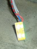
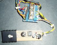
The diodes I used were white 5mm 5000mcd in a water clear package. 2 lamps for each side lamp and 3 for each number plate lamp.
I cut small pieces of Vero board which fit into the original lamp holders, this allows direct replacement. The LEDs are mounted onto this board and wired in series with a current limiting resistor built onto the PCB.
The lamps needed to be directed in a way to give even light distribution. The end result is pure white light with a slight blue tint and low power consumption.
|
|
|
|
|
|
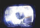
Date: 24/12/03
Project: Xenon head lamps.
|
|
|
|
This saw the end of the dull yellow Tungsten H4 bulbs and replaced them with the newer Xenon filled type.
|
|
|
|
These lamps are not expensive if you go to the correct place, Ebay is good, just be sure to get the E marked type so you’re nice and legal.
These bulbs give out a pure white light with a blue tint giving better visibility and a modern look to the lights.
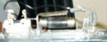
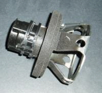
While changing the lamps I found the height adjuster on one side had failed.
|
|
|
|
|
|
I removed the module from the head lamp module and opened it up, the motor inside had completely corroded and seized up. With nothing to loose I took the motor apart and was able to clean up the armature and magnets, I reassembled the motor with a smearing of petroleum jelly and refitted the module. This now works perfectly with no new parts, great!
|
|
|
|
Date: 25/12/03
Project: LED Door markers.
|
|
|
|
As a continuation to replacement of filament lamps and to get me out of the house for an hour or two on Christmas day! I have now upgraded the door marker lamps to LED, again the two diodes were fitted to a piece of Vero board along with a resistor.
|
|
|
|
The PCB was cut in a way so it simply push fitted into the same slot as the stock bulb.
I have found it helpful to flatten down the top of these high brightness lamps, as this gives a wider angle of light output and prevents a bright spot on the diffuser.
The result seems good with the same gains as before.
|
|
|
|
|
|
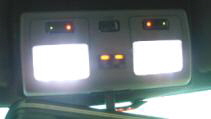
Date: 28/12/03
Project: LED interior lamp.
|
|
|
|
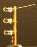
The LEDs are taking over my car! Yes, more nasty yellow bulbs disposed of and replaced with nice bright, white LEDs. As you can see from here, they ARE bright!
|
|
|
|
Today it was the turn of the main interior lamp, this used 6 high intensity diodes per side. These were mounted onto a piece of PCB and stuck inside the lamp housing.
To save damaging the lamp holder, I used a couple of bayonet bulb bases and wired the connections into them, this meant the new LED lamps simply plugged into the stock holder.
|
|
|
|
|
|
|
Date: 30/12/03
Project: LED rear interior lamps.
|
|
|
|
As a continuation of the LED upgrade the rear interior lamps needed to be fitted with the new lamps. I fitted these extra rear interior lamps when I bought the car as the rear seating area had no lighting. These came from a Vectra at a local salvage yard.
|
|
|
|
|
|
Date: 05/01/04
Project: Refitting steering loom & drivers foot well lights.
|
|
|
|
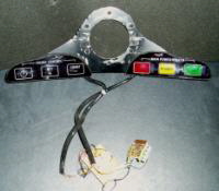
After a successful trial of the steering wheel loom for the wheel mounted control panel, it was time to put it in properly. One point I found was that on the first attempt the outer braid had caught up on the lower part of the steering boss, this I hope to have solved by putting a large piece of heatshrinc tube round it making the shapt totally smooth.
|
|
|
|
|
|
The pic on the left shows the custom boss without the smoothed off shaft, this is what the braid had snagged on, to the right you can see the boss with the new loom fitted into it.
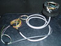
Once installed the loom is fitted into the steering column alongside the standard vehicle loom, the cruise control connections joining where the original wires would go onto the old slip ring system.
The main PCB for the start/stop system is hidden away in the main dash, smaller boards mount inside the steering boss to interface with this, they also incorporate the components for
|
|
|
|
|
|
the cruise control switches, this is a simple resistor network copied from the standard wheel. The loom simply wraps around the steering column as you turn then returned to the unwound state when the wheels are strait.
|
|
|
|
|
|
|
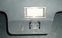
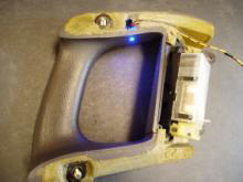
While in the drivers foot well I decided to update the foot well lighting, up until now this had been done with small bulbs mounted in twist type holders and fitted into the kick panel. I did away with the bulbs and mounted a proper fixture in the same place as the old holes.
|
|
|
|
|
|
|
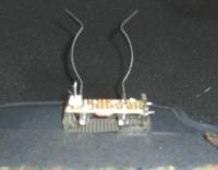
Next out came the LEDs! I mounted 2 blue and two white on a small PCB, this PCB fitted snugly into the lamp holder and had a 3 way connector on it so you can remove the kick panel easily.
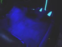
I filed the domed part off the LED and polished the tip, this gives a wider projection angle. The white lamps come on with the courtesy lights while the blue ones come on with the side lights to provide ambient lighting in the foot well, LED illumination is less harsh than neons and less fragile!
|
|
|
|
|
|
|
Date: 11/01/04
Project: Fitment of EL wire.
|
|
|
|
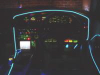
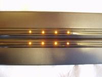
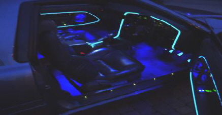
Its raining so time to put the car in the garage and do some dash work! It was time to continue with more EL wire around the rest of the dash, this is a continuing project, this time I fitted the wire around the main dash over hang and the centre console.
|
|
|
|
|
|
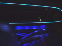
EL wire is a flexible plastic wire that when a high frequency / high voltage is put through it glows brightly. The wire can be cut to any length, is water proof and flexible.
To run the wire you need a tiny inverter, about 2 inches square, this will run about 30 feet of the stuff. These come in various options like constant lit of flash to music.
|
|
|
|
|
|
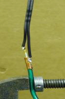
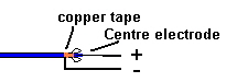
The wire, in my case 2.5 mm size, is made up of a coloured outer sheath, an inner protected wire with 2 exciter wires wrapped around the inner electrode.
To connect the wire to an inverter you simply cut away the sleeve and connect the inverter across the exciters and the inner electrode. The easiest way to do this is by attaching the two tiny exciter wires to a small piece of copper tape wrapped round the outer sheath, this prevents them breaking easily, the middle electrode can be soldered directly onto.
|
|
|
|
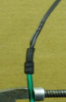
Once soldered I clean off the wire with alcohol. I have fitted the wire to the car so it follows the stitching lines in the trim. To stick the stuff down I first clean the trim with alcohol to remove all dirt and dash cleaners, then I run a small line of contact adhesive along the trim area and along one side of the wire.
Because its a contact adhesive, once both parts have been allowed to cure for about 5 - 10 min’s, when the two parts are pushed together a strong bond is made instantly so, no holding is required.
The adhesive I use can also be removed from the trim without any damage or trace afterwards should you change the positioning etc.
if the trim is likely to be removed in future it is always worth putting a small push connector onto the wire so you can simply unplug it from the loom.
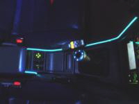
This stuff looks stunning and is still very new on the market so nice and unusual, available in wire, sheet or strip form.
|
|
|
|
|
|
Date: 17/01/04
Project: Alloy wheel lights.
|
|
|
|
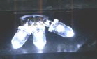
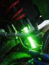
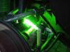
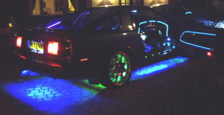
Ever since fitting the under lights I have never been happy with the dark areas around the wheels. The solution was to fit individual lamps behind each wheel. for this the easiest option and by far the brightest were Cold Cathode Tubes - CCL.
|
|
|
|
|
|
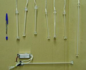
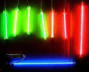
CCL tubes have a tiny diameter, only 3 mm and are available in a range of standard sizes. Because the glass package on its own is very fragile most tubes come encased in protective plastic tube, this also makes them water proof.
The tubes need a high voltage to run them so a small inverter is needed, 12 vdc is pretty much standard, these tubes can be dimmed and flashed with ease.
the packages I use in the Supra are 12” or 6” running off tiny inverters, all of which can run two lamps if desired, however the high voltage leads do need to be kept short, no more than 30 cm or so.
|
|
|
|
|
|
|
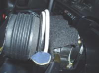
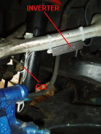
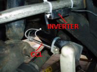
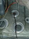
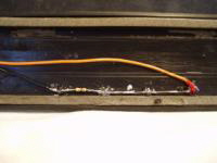
The power leads themselves I ran into the car at the closest possible point and provided local earths inside the car for each lamp. The rear cable pops up through a grommet on each side under the rear seat.
The front cables run behind the wheel arch liner and into the sill space via a small grommet located behind the mud flaps, this wire then enters the car via one of the holes in the sills. Doing this dramatically reduced the cabling required to wire the lamps.
|
|
|
|
|
|
|
|
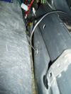
Once the wheels are on and the car is back on its wheels you can’t see the lamps behind the wheels as they are concealed by the large Supra rotors.
|
|
|
|
The positioning of the lamps means you get illumination around the entire inside of the wheel as well as reflection off the ground, resulting in no more dark patches in the ground lighting display. Both the systems are also independent of each other.
|
|
|
|
|
 |
|
|
|
 |
|
|
|
|
Date: 18/01/04
Project: Interior light control.
|
|
|
|
Since changing all the interior lighting to LED, I have had to devise a new circuit to operate the system as the old system relied on the loading from the old bulbs.
this new system is based on an opto being used as a voltage follower, the circuit allows the lights to fade up slowly and dim off even slower.
The system is fully overideable allowing all lights to be set to on or off, as well as this should the car be started, the delay is bypassed allowing the lights to dim off immediately, when the engine is switched off or the car unlocked, the lights are switched on automatically.
|
|
|
|
|
|
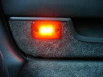
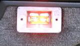
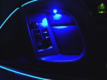
Date: 24/01/04
Project: Door markers and pocket lights.
|
|
|
|
More sunshine! so time to fit the door side markers, these I did in the same way as the red rear side markers.
|
|
|
|
 |
|
|
|
 |
|
|
|
|
|
Date: 07/02/04
Project: Race brake upgrade.
|
|
|
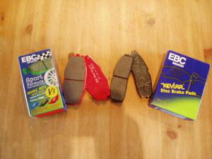
Time to replace the front pads however this time I thought it would be an idea to uprate them as well.
After a little shop around I decided to use EBC brakes, red stuff pads for the front and Kevlar pads for the rear.
As well as being uprated race pads which stop brake fade during high speed braking, these also have the added benefit of less brake dust thus reducing alloy wheel cleaning!
|
|
|
|
|
|
|
|
|
|
|
|
|
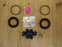
At the same time as replacing the pads I overhauled the front brake callipers, one of the piston dust covers had worn through so it seemed sensible to purchase a service kit from Toyota.
This kit comprises of all rubber seals for both front callipers, its a pretty simple job, just follow procedure in TSRM, the pistons tend to have a build up of rubber from the old seal, this can be removed with metal polish. Just need to bed the things in now!
|
|
|
|
|
Date: 15/02/04
Project: LED rear light clusters and foot wells.
|
|
|
|
|
|
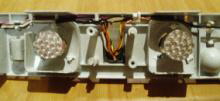
To continue with the ongoing project of eradicating filament lamps from the car, today saw the fitting of LED bulbs to the rear clusters.
These units which I purchased from the US (quarter of price there!) are a direct replacement for the 21 w and 5/21w rear bulbs.
|
|
|
|
|
|
|
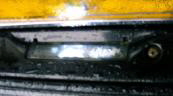
There were a couple of modification needed to fit the lamps, the main one was to mount the lamp holders on the rear of the lamp tray. The original stock lamps are mounted on their side where as these lamps need to point directly forward.
|
|
|
|
|
|
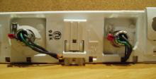
This was a simple mod, I used two spare lamp trays from a donor car and remounted the holders to the rear of the tray, re wiring the loom to the stock plug. This way should I need to change back to bulbs for any reason I can simply refit the original trays.
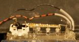
The other mod was to the flasher relay, because the LED lamps do not draw the same currant as a bulbs, the flasher sees a blown bulb fault resulting
|
|
|
|
|
in a fast flash, this was solved by fitting a 470 ohm resistor into the relay PCB, this fools the IC into thinking all is OK.
The bulb fail module also needed to be modded to stop the lights on the dash from coming on, this is simple, you just remove the violet and black wires from the plug on the unit. You can’t just disconnect the module as the cluster power is switched through it.
|
|
|
|
|
|
|
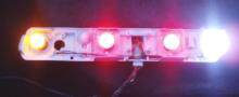
These LED lamps offer many advantages, the whole lot on at once draw less current than one 21 watt bulb! Add to that they will never blow, there is also the added safety that the LEDs fire instantly, this means the stop lamps come on sooner which is always a good thing!
|
|
|
|
|
|
|
|
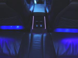
The second task of the day was to update the rear foot well lighting, this up to now has been two green 1.2w lamps.
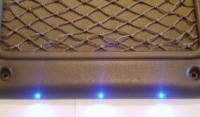
I have decided to do all the foot well lighting blue now to mach the door pockets, for this I am using ultra bright LEDs. Already I have swapped the front ones for blue, for the back ones I fitted 3 LEDs into the bottom section
|
|
|
|
|
of each front seat back. These LEDs are filed down to the same depth of an LED clip and fitted through the trim.
This method makes the Fitment invisible even when the seat is put forward. Filing down an LED also makes its light spread wider which is much better for larger areas and prevents “hot spots” of light. To prevent dark areas under the seats I also fitted 2 LEDs under each front seat.
The wiring is connected via a 2 pin plug to the seat loom so the backs can be removed with ease.
The blue looks great at night and now floods the foot wells.
|
|
|
|
Date: 21/02/04
Project: Door handle lights & white fog lights.
|
|
|
|
|
|
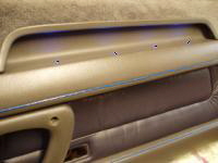
Door cards off again this time to fit blue accent lightingt o the door handles. This was relitively simple as the handles are buitl around a strong inner plastic former.
This former provided a strong base in which to mount a flush blue LED, this provides a subtle blue glow to the handle area and extra visibility of window switches.
|
|
|
|
|
|
|
|
|
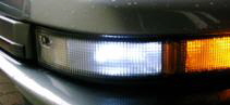
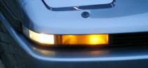
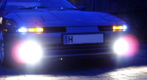
Today also saw the removal of the yellow front fog lamps so as to change them to white ones.
This is a real simple thing to change, the yellow colour of the light is provided using a yellow glass capsule mounted in the lamp holder. The holder comes out on two screws allowing you to take the yellow capsule out of the assembly.
Put in some 6000K HID lamps and you have nice white fogs.
|
|
|
|
|
Date: 25/09/04
Polished sill trims.
|
|
|
|
|
|
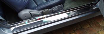
Thanks kindly to a member of the MKiiisupra.net forum the car had a nice set of polished stainless sill trims fitted today.
These fit over the existing plastic trims and use same screw mounts
|
|
|
|
|
Ofcoarse not wanting to lose my existing lighting from the old trims I fitted the new ones with 5 colour changing LEDs. When the door is opened these come on and fade through every colour in the rainbow!
|
|
|
|
Date: 07/10/04
New front disks and pads. New exhaust system.
|
|
|
|
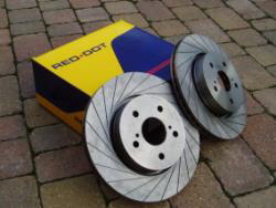
Due to age it was time to fit new disks to the front of the car also, the EBC pads fitted to the front of the car had worn out already! shant be using those again!
I went for 20 groove red dot disks, these were a direct fit with no problems. To compliment these I fitted Mintex race pads.
Braking again is hugely improved with no fade at all from high speed, the grooves make braking slightly noisey but its not a nasty noise its a pleasent rumble as the grooves go under the pads.
|
|
|
|
|
|
|
|
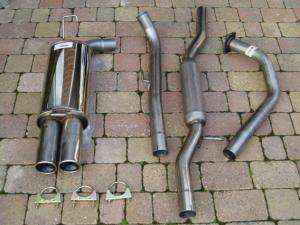
Due to the rather premature end to my HKS Hyper Muffler exhaust thanks to rust I found myself needing a new exhaust.
Having had the large single exit for years I decided to go back to a pleasent twin 2.5” exit,. this came in the form of a full Mongoose system.
This replaces the whole system from turbo back with a solid stainless steel pipe. The whole thing went on a dream with no problems what so ever.
Quality is good and it sounds great!
|
|
|